
The pitot and angle of attack lines need to be run through the left wing up to about the 10th rib. I've pretty much decided that I'll be installing Garmin avionics, so I went ahead and bought a GAP 26 pitot/AOA probe that will give me both ram air for the pitot system and angle of attack that will also function as the stall warning system (I probably won't be installing the stall warning microswitch included with the wing kit).
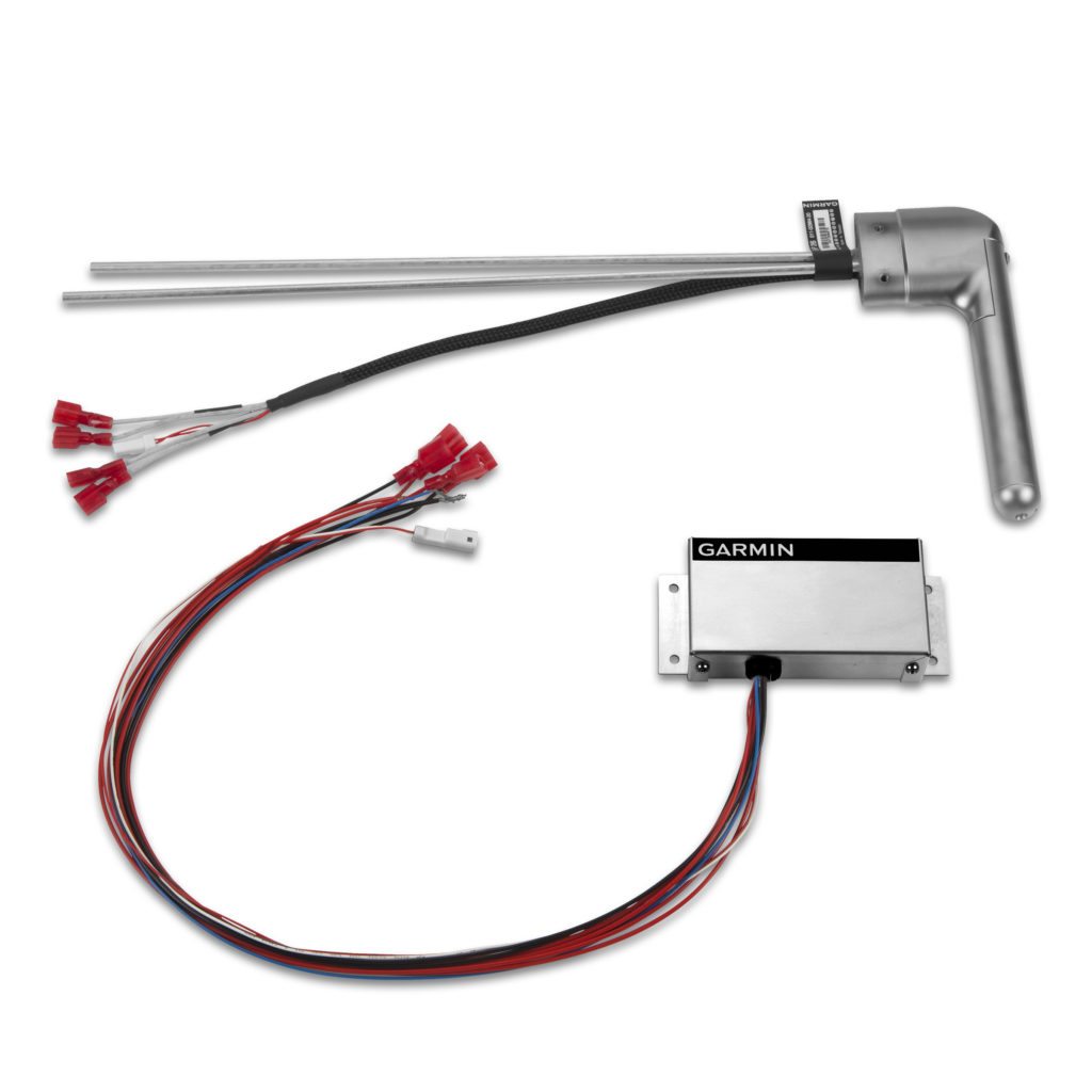 |
| I also went for the heated and regulated model. The regulator maintains optimal temperature without melting anything, plus it gives me a reminder annunciator through the G3X when it's cold enough for icing and the pitot heat is off. |
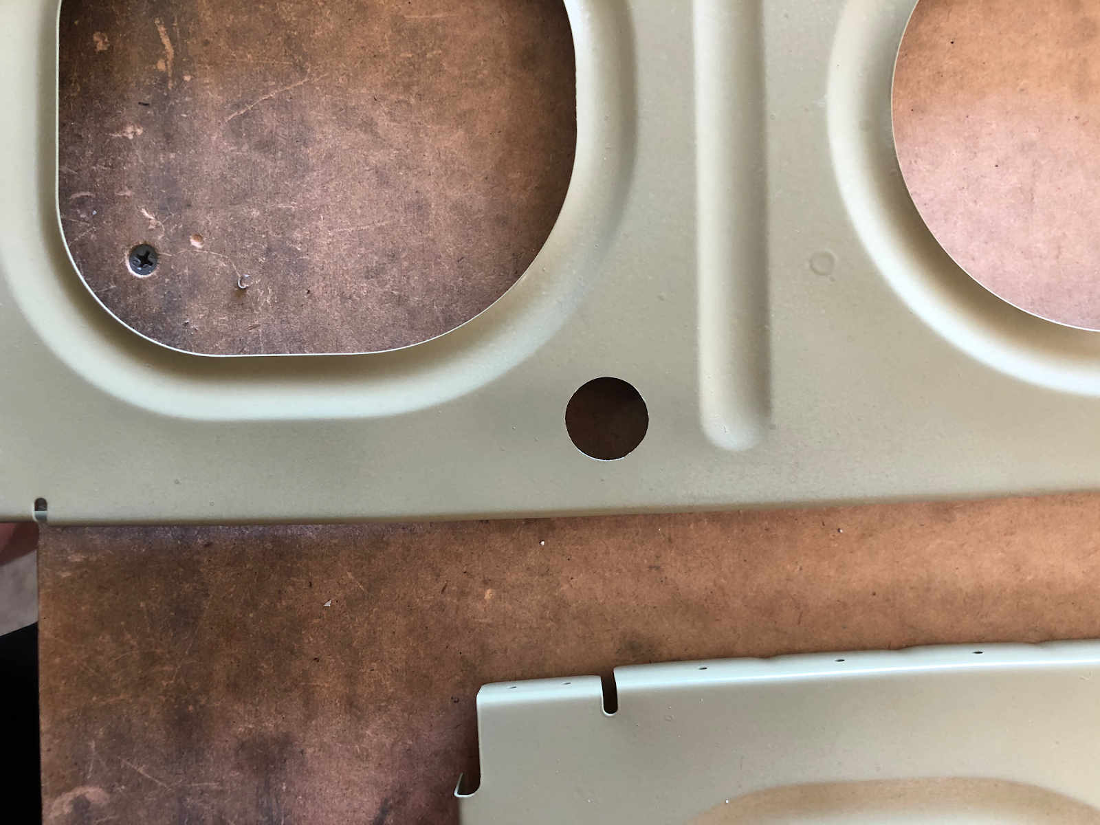
There's already a 7/16" hole in each rib for a 1/4" pitot line, so I only needed to enlarge the neighboring tooling hole to 7/16" so I could run the AOA line right beside it. The unibit made quick work of that. These holes will have snap bushings installed so I can run the lines without fear of them chafing or being cut by the ribs.
 |
| The original tooling hole vs. the enlarged 7/16" hole for the AOA line. |
There are a lot of options for ways to run wires through the wings, but most builders opt for some kind of conduit to keep wires bundled together and avoid chafing/cutting the wires on the relatively sharp ribs. Van's method involves either enlarging the tooling holes and running wires through snap bushings or drilling an extra hole in each rib for running a nylon conduit. Some builders choose not to drill these holes and instead attach a nylon or PVC pipe conduit through the existing large holes in the ribs, but those installations usually look pretty ugly to me and I would be concerned about possible interference with the aileron pushrods.
I opted for the Van's nylon conduit. Van's has a nice article on their website for guidance on drilling holes in the wing ribs, so I drilled a #30 pilot hole in the approximate location shown in the article.

Since all the ribs have the same tooling holes it was pretty easy to cleco them together and match drill this hole to all 27 other main ribs so the conduit will lay in a straight line once it's run.

Finally, I enlarged the hole the 3/4" using the unibit and made sure it was deburred.
Now that the ribs are ready to be riveted, it's time to make sure the wing stands are ready to accept the wing skeletons. I picked up some lag screws and washers and installed some 1/8" aluminum angles per the plans and added braces to keep them strong. These need to be adjustable to remove any twist from the wings later on. I kept the forward hole at 1/4", but I enlarged the aft hole on each angle to 5/16" so I have a little room for adjusting the angles up and down. With the brace supporting things from below and a few steadfast lag screws, these wings ain't goin' nowhere.
 |
| It may look flimsy, but I'll probably be able to jump up and down on this without it budging. |
 |
| With the enlarged holes allowing the angle to move, I can set the angle down... |
 |
| ...or up as needed. This should be more than enough movement to correct any twist in the wings. |
Once I had the horizontal angles attached to the 4x4s I leveled the angles as best I could and laid a wing spar across just to make sure everything fit correctly.
 |
| It works! Even if the spar itself sags a bit. I'll be putting some jacks under the wing skeletons to keep this from happening. |