April 17, 2020

Fuel cap flange countersinking, fabricating vent line clips

Moving onto the fun stuff now. The holes around the fuel cap flanges obviously need to be flush, and the flanges need to be machine countersunk to accommodate the dimpled skin. Countersinking the anodized flange reveals the bare aluminum underneath which makes for a cool color contrast.


Initial fit was good and the flange appeared to be in place...


...but I noticed a small gap between the skin and the flange when looking at it from the side.


At first I assumed my countersinks weren't deep enough, but a couple of attempts to deepen the countersinks resulted in almost no difference with the gap.


Since the flange is machined to match the final curvature of the tank skin, I figured that the curvature is probably different when the tank isn't attached to the ribs thus my countersink depth is probably fine. Looking at the fit from through the hole itself, it was difficult to even know that a gap existed. The gap will most likely be sealed by the tank sealant I apply here when I rivet the flange to the skin, so I decided to stop worrying about it and move on.


I countersunk the holes in the flange for the other tank and got similar results. 


The small clips meant to secure the very end of the vent line needed to be fabricated, so I grabbed some scrap sheet and cut some small strips. I bent them into shape around a drill bit that was roughly the same diameter as the vent line. Some strategically-applied force with my fingers and later with some pliers gave me roughly the shape I needed.


I did my best to make them as round as possible but it was difficult to keep them from getting sharp bends.


Once they're riveted in place they should work well. Their only purpose is to secure the end of the vent line and they'll certainly do that just fine. For extra insurance, I may use a dab of tank sealant between the vent line and the clip just to keep things stable.

April 15, 2020

Match drilling and riveting ring stiffeners, match drilling fuel drains

Removing a huge circle of material from the inboard ribs also reduces the structural strength of the rib by a considerable amount. To mitigate this, a stiffener ring is added around the cutout that not only strengthens the part but also provides for nutplates that allow the fuel pickup/fuel sender cover plate to be attached to the rib.

The first step here is clamping on the cover plate and match drilling the final screw holes. I started by using the #21 bit to match drill these holes since it fit perfectly through the prepunched holes in the plate. The holes were large enough to accommodate the screws that will be used to install the plate, but tight enough that the screws couldn't just be pushed through and had to be threaded into place. I took advantage of this by using the screws as temporary fasteners (the #30 and #40 clecos didn't work here) while match drilling, but I went back after I was done and enlarged the holes to their proper #19 size.


Next was clamping on the stiffener ring and match-drilling the holes for the nutplates through the rib.


The cover plate needs to be attached flush to the outside of the rib to seal it, so the nutplates have to be installed with AN426 flush rivets. This means dimpling the rib and then machine countersinking the stiffener ring to allow the ring to also sit flush against the inside of the rib. I countersunk the ring and checked to make sure it fit flush with the rib.


I realized that I hadn't actually deburred the ring yet, so I took care of that with the scotchbrite wheel before cleaning the parts with MEK. Finally, I riveted the nutplates to the ring and the rib using the squeezer.


Next up was drilling holes for the fuel drain at the lower inboard corner of each tank. The main drain hole is already there, but the six holes around it need to be match drilled to rivet the drain itself to the skin. These could easily have been prepunched from the factory, but then again I did choose the RV-7 kit over the RV-14 kit so I've come to expect stuff like this.

Luckily, this is a quick and easy job. I did my best to clamp the drain as perfectly centered to the hole as I could, then drilled through the holes in the drain into the skin. 


To help align the holes before drilling (the orientation of the holes really doesn't matter all that much, I just wanted the rivet pattern to match the one on the tank flanges) I drew a line thorugh the center of the drain hole.


I then repeated the whole process for the drain for the other tank.


To deburr the holes and to prepare for sealing and riveting these things later on, I took the soldering iron and removed the vinyl around the rivet holes.

April 13, 2020

Drilling and cutting holes in the inboard fuel tank ribs

The inboard ribs come from the factory with only a couple of tooling holes in them, but more holes need to be made to accommodate some of the features that make this thing a fuel tank.

I decided to start with the much smaller hole for the vent line. Using the approximate location called for in the plans, I drilled a #40 hole in one inboard rib and then match drilled it into the other rib so they would be consistent.


The unibit then took care of enlarging the holes to final size for the vent line fittings.


I then moved on to the much larger access hole, which not only allows access to the inside of the tank should maintenance have to be performed later on, but is also the location for the float fuel senders I'll be installing. I was a little hesitant when it came to cutting these since the plans recommend using a fly cutter on a drill press, two things that I did not have at the time. I went out and bought a fly cutter from Harbor Freight (which ended up being quite the interesting experience thanks to this whole COVID-19 deal), but I ended up not getting the drill press since I hadn't really needed one throughout the rest of the build thus far and I didn't see myself using it regularly for the rest of it.

So I ended up doing what most people do NOT recommend, and that's using the fly cutter in a handheld cordless drill. And you know what? It worked just fine.

The hole to be cut needed to have a diameter of 5 1/4", just large enough to remove the ring-shaped stiffening protrusion on the rib. The packaging for the fly cutter I bought states it does a maximum diameter of 5", but I was able to get it to 5 1/4" by removing the rubber o-ring on the end. The other slight modification I made was to flip one of the blades around. I didn't want to have to painstakingly match the blades to the same track, so this allows just one blade to give me a clean, precise cut while the other blade counterbalances it without cutting anything.


I was a little nervous about doing things like this, so I decided to test the setup with a scrap sheet of aluminum just in case this was actually a stupid idea. I figured that if things went horribly wrong on here, I wouldn't have messed up one of my parts and I could then just buy a drill press.

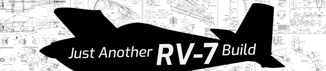
I found the exact center of the circle I wanted to cut and drilled a pilot hole in which the 1/4" bit on the flycutter could stay centered while cutting. A slow drill speed and light pressure allowed me to get the cut started and check for the proper radius before going any further.

The larger circle is the result of me messing up the initial setting on the fly cutter. Good thing I took this practice run first!

Once I was sure the cut was accurate, I gradually increased the speed and pressure of the drill while keeping it a perfectly perpendicular to the piece as I could. This took patience since the drill constantly wanted to move around. Toward the end of the cut, the blade started catching on some parts of the circle. I realized that these areas were where the blade had fully pierced the piece.

You can see exactly where the full cut has been made and which parts still need to be cut.

I used extremely light pressure and a faster speed to chip away at the parts that needed further cutting until most of them were taken care of. Eventually I was able to just flex the piece a little until the circle popped off like a pull tab off of a soda can.

Everything went better than expected.

Cool, it worked! Now for the real thing.

I drilled a pilot hole in the exact center of the circle to be cut and again started with light pressure at a slow speed to check the size of the cut.

Looking good. Proceeding as planned.

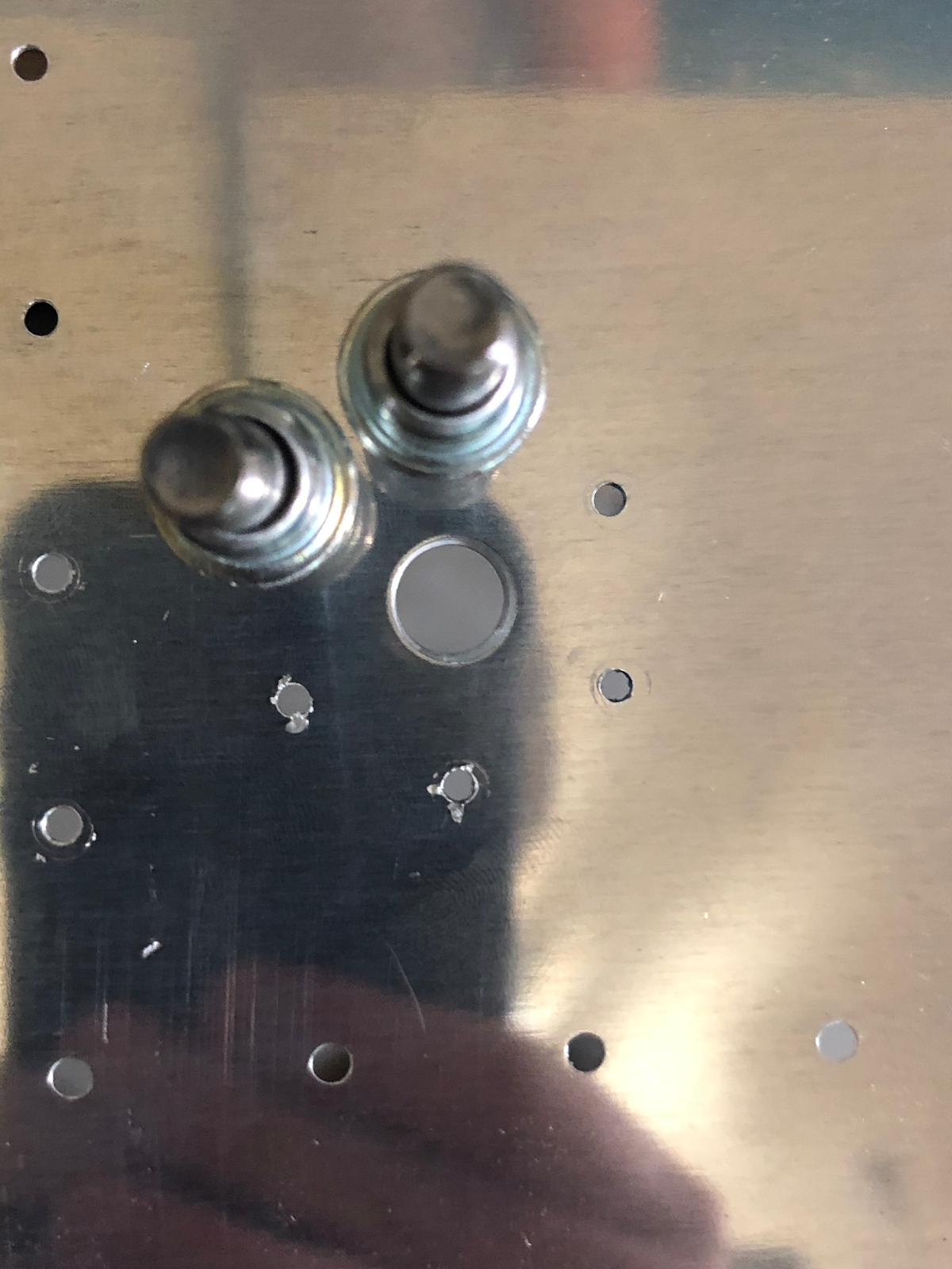
From there I did exactly what I did on the practice piece, and soon enough I had a nice big hole cut into the rib.

Success!

To double check things, I clamped the reinforcement ring in place.


Rinse and repeat for the other rib and boom, done! These things are SHARP right after cutting, so I made liberal use of the deburring tool and a scotchbrite pad to smooth things out lest I end up with some nice lacerations while celebrating.


Now I'm not saying that this is the recommended way to do this, but it did work for me. If you already have a drill press or have easy access to one it's probably best to just use that instead of messing around with a handheld drill. That said, this is a good lesson for me that I don't always have to religiously follow the advice of other builders. Sometimes it's worth exploring and experimenting on your own to find out what works for you.

April 12, 2020

Fabricating tank attach angles and nose reinforcement plates

Since the fuel tanks form the inboard leading edge of each wing, they need to have some way of attaching to the fuselage. Enter: the T-405 tank attach angles. The angles start life as a single 2"x2.5" aluminum angle, which of course must be cut and shaped by the builder. 

The angles have two distinct shapes that the builder must make: one side of the angle fits into the leading edge of the inboard fuel tank rib while the other is a simple rounded shape that will bolt to another angle coming off the fuselage.


To start, I cut the single angle into the two angles I'll need. The T-410 plates included in the kit are already shaped and fit nicely into the leading edge, so I traced their shape onto each piece.


For the other side I did my best to match the shape and dimensions in the diagrams.


I happened to have a compass in my tool chest that made it easy to etch a nice 1-inch radius per the plans.


Ready to cut.

I used the bandsaw to start, cutting around the marked lines to get the angles to their rough shapes.


From there I used a combination of the vixen file for removing the most material and the scotchbrite wheel for final shaping and polishing.


Once I was happy with each shape, I test fitted them into the inboard ribs. The fit doesn't have to be perfect since the positions of the angles that attach to the fuselage will be determined by these angles.


Moving on, I started work on the T-410 plates. These are the plates that will seal and reinforce the inboard and outboard tank ribs at the leading edge, so they're shaped to fit the skin. They come attached to the inside of the T-407 rings that will reinforce the large cutout I'll soon be making in the inboard ribs. Apparently builders used to have to fabricate the plates themselves, but Van's realized they had enough room to just cut them from the same piece as the ring. Whether or not that's true, it still means more efficient manufacturing, less wasted aluminum, and less fabrication for the builder - a win all around!


Once separated and deburred, I removed the vinyl from each then reassembled each fuel tank so I could check the fit for each plate.

Without the plates, you can easily see how many open spaces there are here.

With the plate in place inboard the rib, most of that space is filled and the remainder will be closed and sealed when the tank sealant is applied during final assembly.

I can't really clamp the plates in place with the skins in the way, so I marked the location of each plate with sharpie so they would be in the right position when match drilling them to the ribs.


For drilling the plates, the plans don't really give a hole pattern. I decided to go with something similar to the pattern that the plans suggest for the T-405 angles. This pattern as is works for the angles, but it accommodates the angle portion and thus doesn't completely cover the area of the T-410 plates. The inboard T-410 plates have to use the same pattern since they'll be attached using the same rivets as the T-405 angles, but I decided to modify the pattern a bit to cover the whole area of the outboard plates. 


These plates are technically meant to be installed after the inboard and outboard ribs have been riveted into the skins, so when making the modified pattern I wanted to ensure that any dimples and rivet heads coming inward from the skin wouldn't interfere with the rivets for the plates. To do this, I made sure that the holes I drilled would allow the straight rivet set to clear 1/8" from the edge of each plate. Each skin-to-rib dimple+rivet shouldn't encroach more than 3/32" inward from the inside face of the rib flange, so 1/8" gives ample clearance for the set when the plates are being riveted.


After punching and drilling one plate I clamped the other one to it and match drilled for a perfect match. The final pattern for the outboard plates looked something like this.


I positioned the plates on their ribs and match drilled the pattern.


The process is much the same for the angles. While test fitting the angles to the ribs I marked where the rivets would interfere with the angles and made sure to keep the rivet pattern away from these areas. The aftmost row of rivets had to be moved up a bit to ensure that the flat underside of the rivet heads wouldn't interfere with the curved transition to the flange of the angle. 


Again I drilled one angle then clamped on the other one for match drilling.


I then clamped each angle to its rib and match drilled.


To finish the job, I removed the angles and clamped on the reinforcement plates so I could match drill using the holes I had just put into the ribs.