May 27, 2019

Dimpling and countersinking flap pieces, preparing for final assembly

Before I could start riveting the flaps, I needed to finish countersinking the holes on the bottoms of the main spars since I decided to prime everything first. I think I've finally gotten the hang of machine countersinking since I'm now able to get fast, quality results without letting the holes get oblong.

The contrast between the green primer and bare aluminum looks so cool.

The plans recommend making a flap stand to assist in holding the flap steady during riveting, so I grabbed the wood left over from the large wing crates and cut out some V shapes using the ribs as a template.

Screwing two boards together during cutting allows for two identical pieces.

At first I used some tiny pieces of scrap wood to hold up the two pieces, but these proved to be way too flimsy to be effective.


Instead, I used some more wood from the wing crates and screwed the pieces together. This proved to be way more solid.

The main board has a crack running down the middle, so the extra pieces screwed to the middle are to keep it from splitting any further.

To round out the day, I dimpled the rest of the ribs and spars for the flaps. Next up, riveting.

May 22, 2019

Ailerons complete! Finishing aileron assembly

The next step in getting these ailerons together was riveting the aft skin onto the top of the main spar and under the top side of the nose skin. I tried holding the whole assembly as flat as possible to the table while I clecoed on the skin so there would be as little twist as possible here.

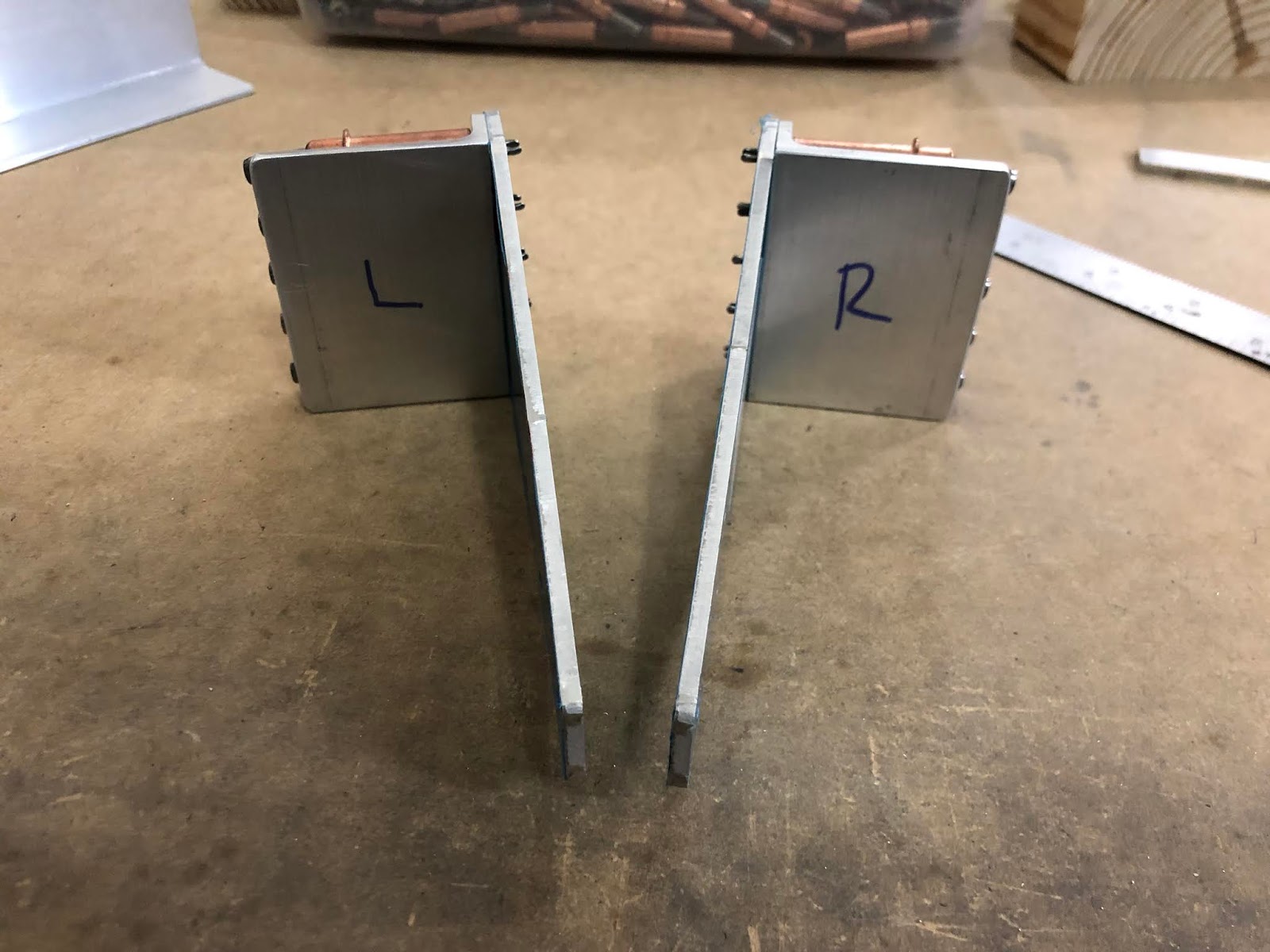
For propping up the assembly for riveting, I took yet another suggestion from Mike Bullock's build log and made some vertical stands for the aileron that were tall enough the hold the nose skin off of the table. I used some round head screws to secure each end of the spar to the stand, then used clamps to secure the stands to the workbench.


The result was a remarkably solid assembly that wouldn't move a millimeter while I riveted everything.


Now I just had to figure out how the heck I was going to rivet the skin, especially toward the middle of the spar. Since I wasn't willing to buy any kind of specialized bucking bar for this task, I decided to modify the one I have to make it work better for this application. The only issues with the stock bucking bar are a) it's very difficult to keep a grip on the thin bar when your arm and hand are wedged into the tight interior space, and b) the bar is small enough to fall between the lightening holes and cause damage to the nose skin underneath while making it difficult to retrieve.

To solve both these issues I took a small wood block, sanded it smooth on all sides and edges to prevent scratches, then taped it to the bucking bar so it would sit flush on the bottom edge. This gave me a bucking bar that was easy to grip, easy to keep square, and wouldn't fall through the holes in the spar.

The masking tape wasn't my first choice, but it worked just fine.

Now came the difficult part - actually riveting this thing. In order to get the bucking bar into the assembly I had to pry the bottom skin from the spar and slip it in place, though that's the easy part. The worst part of the whole process is having to maneuver my whole left arm into this space to hold the bucking bar in place for riveting. After some trial and error (and after putting a couple of old socks on my arm to keep the aluminum edges from digging into my skin) I managed to find a position that was comfortable and stable enough to work.

This is what I was dealing with. It's hard to see what you're doing, but I still managed to get decently consistent results.

Not bad for working blindly!

I never get tired of seeing lines of rivets slowly become finished.

The modified bucking bar worked beautifully, except it wasn't able to stay flush for rivets directly under or adjacent to the stiffeners. I skipped those until the rest of the rivets could be set, then I removed the wood block from the bar. I could set the bar flat on the spar and it would fit neatly under each stiffener so I could set the remaining rivets.

As easy as this was, I asked myself why I didn't try this for the rest of the rivets. The main reason was the slight acute angle of the spar which causes these rivets to be slightly crooked when set this way, so my earlier method is still preferred.

Once the line of rivets on the top of the spar was finished I squeezed the rivets attaching the leading edge skins to the nose ribs.

This was a ten-minute job, a cake walk compared to the rivets on the spars.

Next was blind riveting the counterbalance pipe to the skin. I flipped the aileron over and made sure it was laying flat, then broke out the CS4-4 rivets and my blind rivet puller. I'm glad I dimpled the skins here because all of the rivets ended up laying almost perfectly flush. Finally, I could close out the bottom skins by blind riveting them to the spars. Once again I made sure each aileron laid flat before starting and I kept checking this as I worked.

Using a hand rivet puller for both ailerons (around 84 CS4-4 rivets pulled) was murder on my wrists. A pneumatic rivet puller would have been much appreciated here.

At last I had both ailerons finished!


Since I definitely didn't want to try hanging these on the wall with their heavy counterbalances, I cleared off the top part of some shelves and stored them up there. To prevent moisture collecting from skin-to-shelf or skin-to-skin contact I made some cardboard spacers to create a small gap between each surface. If I have to continue storing these in the garage then I'll need to be vigilant for corrosion.


May 18, 2019

Dimpling aileron parts, starting aileron assembly

A full five days later and the primer is definitely cured at this point, so it's time to start the final assembly of the ailerons. First up, dimpling the skins, spars, and ribs.

The counterbalance pipe will be blind riveted to the inside of the nose skins with CS4-4 rivets, which have a countersunk head. The plans say that the skin will deform to fit the countersunk holes in the pipe, but I took a page from Mike Bullock's build log and used the male #30 dimple die and a hammer to dimple the skins (the countersunk hole in the pipe acts as the female dimple die).

This worked way better than I had anticipated. One tap was all it took!

Perfect.

I moved on and riveted the nose ribs to the counterbalance pipe for the right aileron. The plans suggest bending the small tabs on the ribs out of the way to allow room for the rivet puller, so I used the hand seamer to accomplish this. Once the rivets were set, the rib was easy to bend back into place.

I quickly realized that I had gotten a little ahead of myself since I hadn't yet dimpled the ribs. That was an easy fix though since every hole that needed it was still reachable with the squeezer. I took the reminder and dimpled the rest of the ribs and spars while I had the chance.


Next up is getting the doubler plates attached to the spars. The round headed rivets were pretty straightforward, but the plans don't give any specific guidance on what to do for the flush rivets that will attach the platenuts to the back side of the spar. I briefly considered dimpling the plates and the spar underneath, but that would mean dimpling the platenuts too which I wanted to avoid if at all possible. I decided to countersink the doubler plates to allow the rivets to sit flush without having to dimple anything underneath them. The plates are the exact thickness of the rivet heads, meaning they're just thick enough to allow this without negatively affecting the strength of the plate.


At first I tried using the -4 length rivets called out in the plans to attach the platenuts, but the resulting shop head for the first one I squeezed was too thin for my liking. I switched to -4.5 rivets for the remainder and got much better results. As a rule, I should probably at least consider using a slightly longer rivet for any platenuts in the future since I've come across this issue so many times.

-4 on the left, -4.5 on the right. The rivets will be backed up in strength by the torqued bolt that will go into the platenut, so I'm not going to bother drilling out the -4 rivet.

The results look good to me.

With the doubler plates attached I could cleco on the nose skin and rivet the nose ribs to the spar. I did this without clamping anything down at first, resulting in a crooked first rivet. I quickly drilled it out and rectified the issue before proceeding further.

No bueno. Try again!

Once I had done this correctly for both ailerons I called it a night.

May 13, 2019

LOTS of priming for the ailerons and flaps

The remaining aileron parts were long overdue for getting primed, so I planned to at least get them done while I had a good day to do so. I put the leading edge skins, counterbalance pipes, doublers, spars, and ribs on the priming racks, and I realized I had plenty of room to fit most of the remaining flap parts too (which were also ready to be primed at this point, so why not?).

Turns out I could fit every remaining flap and aileron part onto the racks except for the flap spars and skins.

The only metal work left on the flaps was to machine countersink the holes in the bottom of the spars to allow the hinges to sit flush. I briefly considered trying to finish all of the countersinking before prepping the parts for priming, but I was concerned that I'd run out of time if I did that. Instead, I decided to go ahead and prime the spars and countersink them later. I can always spot prime the countersunk holes if I really need to.

With an abundance of parts to prep, I prepared myself for a LONG day in the shop. Scuffing and cleaning everything took around three hours, with an extra hour dedicated to wiping each part with acetone. Planning ahead, I mixed up a bit more primer than I thought I would need in preparation for priming the insides of the counterbalance pipes.

I mixed up around sixteen ounces of primer, which turned out to be more than enough to cover everything.

Priming the initial group of parts only took around twenty minutes. Once the aileron skins and spars were dry to the touch I moved them onto some cardboard-covered sawhorses to get them out of the way, then replaced them with the small lower flap skins now that there was room on the rack. I did the same thing for the rest of the smaller parts on the other rack, replacing them with one large upper flap skin at a time.

Once the rest of the parts were done, I turned my attention to the counterbalance pipes. Priming the outsides was as straightforward as the rest of the parts, but I needed to protect the interior surface of the pipe as well. While scuffing the rest of the parts earlier, I made an improvised tool for scuffing the inside of the pipe by sticking a trimmed-down Scotchbrite pad onto an unbent coat hangar. It works better than it looks.


I taped up all of the holes in the pipe except for one end, then poured in the primer making sure to hold each end tightly to keep any primer from leaking past the tape. At that point I rocked the pipe back and forth while slowly rotating it, making sure that the primer would coat every square inch of the inside surface. This is the same method I'll need to use later on for priming the insides of the elevator and aileron pushrods, so it was good to get some practice now.

The frog tape on the very end didn't work well at all and let a bunch of primer leak out as soon as I poured it in. I actually managed to find a small rubber plug to stop one end and I held the other end closed with the palm of my hand.

At the end of the day I glanced at the clock and realized I had just spent about eleven hours in the shop. It was well worth it though - literally every part that I needed to prime got primed.

Such a satisfying feeling. That's a lot of parts!

Learning from last time, I'll wait 48 hours for the primer to fully cure before I start dimpling anything. Soon enough I'll have both the ailerons and flaps done, then I can move on to the main spars and get the wings started proper.

May 6, 2019

More flap rib work

There are only a couple of things left to do on the flaps, one of which is drilling for the platenuts that will attach the pushrod connecting the flaps to the flap motor.

To start, the hole in the rib needed to be enlarged to 1/4" to accommodate the rod end bearing. From there, I could cleco the rib doubler in place and match drill the 1/4" hole into the doubler.


To drill for the platenut itself I took an AN4 bolt and screwed it into the platenute to hold it in place. I held the platenut as steady as I could to match drill the rib.

The platenut ended up being slightly askew, but it'll be hidden well and it definitely won't bring the airplane down.

Clecoing the one hole, I match drilled the other into the rib.


From there I removed the platenut and clecoed the rib doubler back on so I could match drill the new hole into it.


Finally, the hole I had just drilled into the doubler needed to be machine countersunk on the inboard side. There will be a flush rivet here to allow adequate clearance for the pushrod to glide over this area.

An AN426AD3-6 in place that will be long enough to join the doubler plate and the platenut to the rib.

Rinse and repeat for the left one. Easy enough!

May 1, 2019

Fabricating flap doublers and angles

The inboard corner of the spar is where a lot of force will be applied when extending and retracting the flap, so there are a couple of doublers here that will need to be match drilled to each other and to the spar. The doublers for the ribs are already drilled, but the angles for the forward side of the main spars needed to be fabricated and then match drilled.

There are a couple of large aluminum angles included in the wing kit, so it's important to make sure to use the right one. The plans call for the final piece being 2"x3/4", so the 2"x1 1/2" angle is the one to use here.

Trimmed to length...

...and then to width. I almost burned myself with how hot these pieces got when being cut on the bandsaw.

I rounded off all the corners and ground the edges to their final size and polish, then prepared to match drill the angles to the rib doubler. I clecoed both onto the flap assembly to line everything up, clamped the angle to the doubler, then removed them from the spar to match drill them.


The rib doublers needed to be bent to a 6.3 degree angle per the plans since the inboard ribs are angled inward. I used double sided tape and clamps to fix everything to my workbench, then went at it with some wood blocks and a hammer. I didn't get much progress out of this method though.

Starting to bend...

I switched to using the hand seamer for more leverage and got much faster, more consistent results. With the bends completed I added the assembly back to the flaps and made sure everything was flush before match drilling the doublers to the ribs.


The final step here is to drill the necessary holes into the angles. First, the three holes that connect the spar to the rib are match drilled into the angles. I took off the top skin and used a long #30 bit to drill the middle hole with the bottom skin and the ribs still aligning everything, then removed the skins to gain access to the remaining two holes.


With these holes done I removed the angle and used the diagram in the plans to mark and drill the rest of the holes in the angle. 


Since I didn't want the drill bit to wander out of place, I clamped on a piece of scrap metal with a pre-drilled #30 hole to act as a guide. It worked wonderfully!


The final product was almost exactly like the diagram in the plans.


I clecoed the angles to the spars, match drilled the holes, then called it a night. At this point I only have to drill holes for some platenuts in a couple of ribs, then it's time to deburr and prepare to prime the flap parts.