March 30, 2019

Trim tab complete! Drilling hinges, dimpling trim tab skin, riveting everything

Looking good!

The final major task to complete the trim tab is to fit it to the left elevator and match drill the hinges. I started by clamping the hinge to the trim tab in its appropriate position, then testing the approximate fit by seeing where the forward part of the hinge would end up on the elevator skin.

Fitting the tab is difficult when the hinge is clamped on since the clamp can't fit in the space on the left between the elevator and the trim tab. I had to use some duct tape keep the left side of the hinge in place while I maneuvered the tab into place. Once I was happy with the location of everything I clamped the hinge onto the trim tab.


I match drilled the holes for the hinge with new clecos put into every new hole as I went down the line.


At this point I could disassemble the whole thing and start countersinking the top of the trim tab spar. Just like the trim spar on the left elevator, the spar is machine countersunk instead of being dimpled to allow the hinge to fit flush to the bottom side of the flange.


Normally this would be the part at which I'd prime the parts, but having decided to skip that part I jumped ahead to deburring and dimpling everything. At that point I could start riveting.

Riveting the spar to the bottom of the trim tab skin is one of the more frustrating things I've had to do in this build. First off, I had to use the 2.5" flange yoke which wouldn't fit around the clecos. I had to remove clecos, slide the squeezer into place along the spar, then cleco the skin back down before I could squeeze anything. Second, the yoke will push the rivet out of its hole if the yoke touches the bottom skin, so I had to prop the skin open with some wood blocks to make sure the rivet would stay flush when squeezed.


The most annoying rivets to set were those in the horns where the trim tab will connect to the servo. I could just barely reach the rivets at the front, but there was no way I could have reached the aftmost rivets with the squeezer. I contemplated trying to balance the bucking bar in this little space but I decided to take the easy way out and put some MK319-BS blind rivets here instead.

These probably look a lot better than any attempt at bucking them would have...

With the bottom riveted on I could start the process of matching the hinge to the left elevator itself. This step is crucial to ensuring you have a trim tab that will have the travel it needs while staying in line with the trailing edge of the elevator itself. I grabbed the same piece of aluminum angle I used when I was sealing the rudder trailing edge and I fixed it to the elevator to keep everything in line.


With the tab in place I clamped the hinge to the elevator and checked the edge clearance on the holes to be drilled. I had drawn a line on the forward half of the hinge that showed approximately where I wanted the holes to go, and thankfully everything lined up perfectly.


Starting at the clamped end (since the other end was loose and couldn't be clamped) I kept everything as still as possible and match drilled the hinge, putting in clecos as I went down the line. With the hinge holes drilled and clecoed I could remove the angle and make sure the trailing edge was still straight.

Perfectly straight, good to go.

Being very careful, I drilled and clecoed the holes for the inboard tabs.


At this point I took the trim tab off the elevator and riveted on the aft hinge.


There are no dimensions I could find for the holes on the outboard tabs, so I did my best to put in two holes that would adequately hold both of the tabs down while maintaining adequate edge distances.


I ran into an issue at this point. The plans state that CS4-4 countersunk rivets are to be used here, but the tab is now closed out and there's no way for me to dimple these holes. The skin is also way too thin to machine countersink enough for the rivet to sit flush without enlarging the hole. I briefly considered skipping the countersunk rivets and going for round head rivets instead (this would have worked for the holes on the inboard side), but I realized that this might cause clearance issues between the outboard side of the trim tab and the left elevator skin.

If I had had the foresight to read ahead I may have been able to dimple these before I riveted the tab closed, but I came up with a compromise. Since I couldn't fully machine countersink the hole, I decided to only do it a little to give the countersunk heads a good foundation. Instead of using the countersink cage I took my hex shank deburring bit and gave the hole ten good rotations with a small amount of pressure to give it a nice chamfer without enlarging it.

A small countersink is better than no countersink.

It's not as pretty as a fully flush rivet, but it will keep things secured just fine. It's mostly an aesthetic issue as this point, one that won't be noticeable unless one looks closely.


At this point I took the opportunity to rivet on the forward part of the hinge to the left elevator...


...and finally I reattached the trim tab itself to the elevator. It's done!


Per the diagrams I made a bend in the lower skin of the trim tab to allow it to clear the trim spar and its rivets when enough nose up trim is applied.

Neutral trim...

...and nose up.

Finishing this section, I drilled and riveted the tabs to closeout the left elevator cutout. The red marks show where the rivets in the trim tab are when the tab is at neutral, so I made sure to locate the round head rivets in a place that wouldn't cause interference.


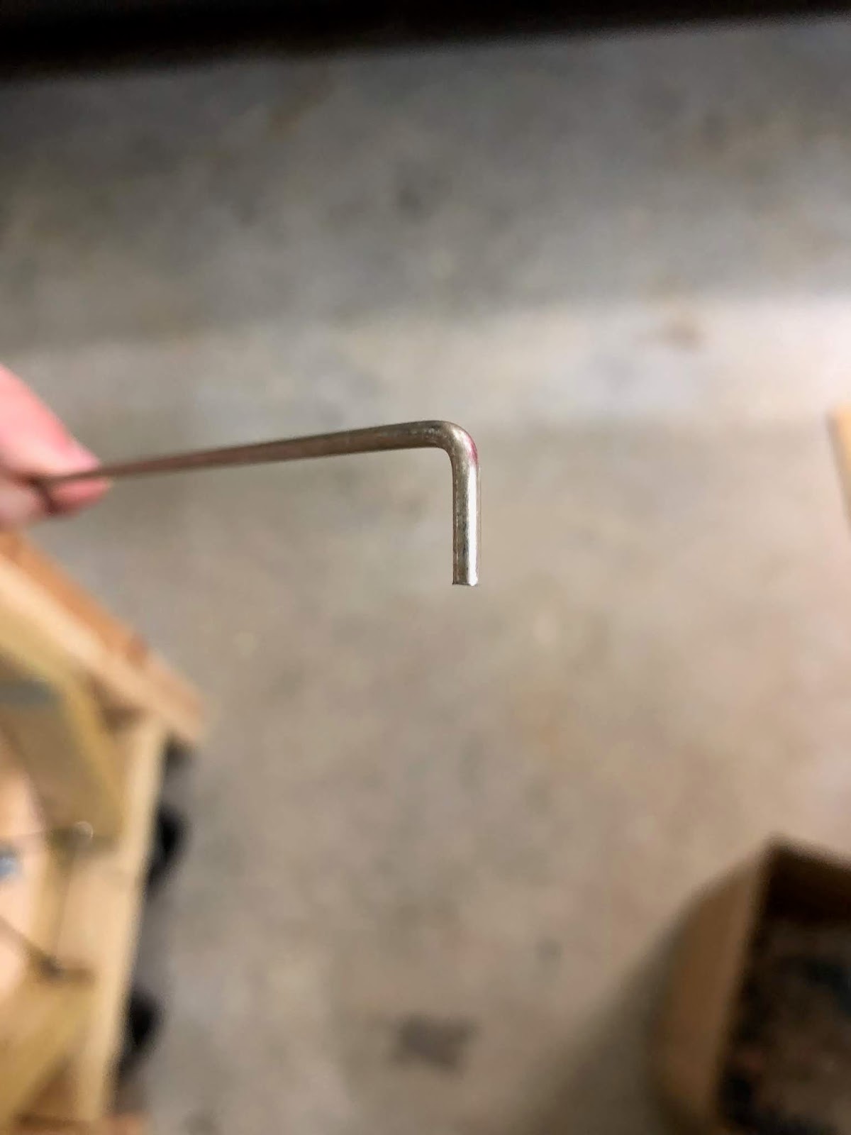
Although it isn't necessary, I also made a 90-degree bend in the temporary hinge pin with the hand seamer. I'll have to make a couple of bends like this when I get the final hinge pin in my fuselage kit, so this was good practice.

March 28, 2019

Starting the trim tab, bending trim tab skin and its tabs, match drilling

At last, I'm at the beginning of the final subassembly of the empennage kit. The trim tab is small, but a lot of work goes into completing it and getting it installed on the left elevator.

At first I considered priming the trim tab parts, but I decided against it. I had a limited amount of time to prime the parts before the next round of storms and humidity rolls in, and I still had to deburr everything (a 1 to 2 hour job by itself) before even starting to prepare the parts for priming. My goal was to finish the empennage and start on the wings by the end of March, so there was no way I'd be able to get the trim tab done by then if I spent a lot of time priming it. Besides, the trim tab is cheap and easy to replace if it ever does get corroded.

Work begins by bending the skin to fit its spar. On the large bender, the smaller tab is unsurprisingly a lot easier to work with than the elevator skins.

Almost there...

Perfect!

Step 2 is to bend the inboard and outboard tabs much like those on the left elevator skin. The smaller bending block I used for the inside of the elevator skin would work fine on the shorter outboard tabs, but the longer inboard tabs would need a longer block to bend the whole tab at once.

The larger block I had used for the outside of the elevator skin was long enough to do the job, but it would need to go on a diet before it could fit all the way into the skin.

Just a little too thick for this application...

A quick slice with the bandsaw and a round of sanding later, the block fit into place. I stuck the all-important double-sided tape on the blocks and clamped the tab to the workbench, then went at it with a block of wood.

A much better fit than before.

A good start...

...and this was as far as the wood block would bend it.

Finishing the bends with the rivet gun left a slight waviness like on the left elevator skin, but it's purely aesthetic and shouldn't affect the functionality of the trim tab itself.

Looks meh, but will probably function just fine.

The smaller tabs turned out much better with a much straighter crease on each side.


My best bend to date.

Thus ended the saga of bending tabs. I didn't get terrible results, but I side with many other builders in that I wish Van's would redesign this piece to have riblets instead of making people bend the tabs. Weight is likely a consideration since the extra ribs and rivets would add maybe an ounce or two of weight, but the results would be far more consistent. Not to mention that the trim tabs on most certified aircraft seem to use ribs. If I end up doing another trim tab for whatever reason then I'll probably go the riblet route and skip this mess entirely.


The final task of the night was match drilling the appropriate holes. When searching for the horns that will connect the trim tab to the servo in the elevator I discovered that I had a pair of very similar parts. The plans and the associated diagram mention removing half of the E-717 and E-718 horns when using the electric trim instead of the manual trim, but there are two horns included in the electric trim subkit that are already trimmed to size.


I clamped the horns in place and match drilled everything to the skin. Those aftmost rivets are going to be a chore to set.

March 27, 2019

Finishing left elevator riveting (mostly), drilling a hole for trim servo wiring

The riveting process continued with the counterbalance skin and ribs, pretty much identically to that of the right elevator. Since my squeezer was still set perfectly for the -3.5 length rivets, I squeezed all rivets of that length on the ribs and also on the trim spar before moving on to the longer rivets in the assembly.

Before riveting on the trim spar and closing out the assembly, I checked the fit of the electric trim servo on its mount.

Beautiful.

While doing this, I remembered that some builders had drilled an additional hole in the spar around this area. The hole that's already in the spar is there to allow for full travel of the servo jackscrew, and the plans show the wiring for the servo being routed through this same hole. I don't feel so good about the wiring being that close to the moving jackscrew, and other builders have noted that this wire routing may eventually cause chafing of the bent wires as the elevator moves up and down. I decided to drill an extra hole pretty much directly forward of where the wires will come out of the servo, and this happened to be right in the hole for the elevator horn.

The stock hole for the jackscrew. The servo fits perfectly.

I made a pilot hole using a #30 bit, enlarged it to #12, then drilled it to final size (1/2") using the unibit. It's definitely a good thing I did all that drilling while the skin was still open. I doubt I would have been able to get all of those metal shavings out if it was closed up! There end up being a slight chamfer on the edge where the unibit bit into the metal and went slightly askew, but the snap bushing I'm going to put into this hole should cover that up.

The added 1/2" hole for the servo wiring.

The last rivets to set were those that connected the trim spar to the E-705 inboard rib. For now only the lower side gets riveted since the hinge for the trim tab still needs to be match drilled and installed. With those done, the left elevator went into storage until I finished the trim tab.

Working as intended. The stand was the better idea versus mounting these on the wall.

March 26, 2019

Starting left elevator riveting

After a long day at work I only had a couple hours to spend on the project, but I managed to get the final assembly started on the left elevator. I had to file away part of the leading edge tabs next to the counterbalance skin on either side since they were scraping against one another. It's probably not a huge deal, but I don't need anything adding to the stressful experience that is rolling the leading edges of the skin.

Needs some work...

Much better!

The process from here is pretty much identical to that of the right elevator: rivet the counterbalance skin to the main skin, place the counterweight with bolts in place into the counterbalance skin, rotate the skeleton into place, and put clecos in everything.

I went to cleco the trim spar into place when I noticed a small deformation of the lower skin near the closeout I had just finished.  I used the hand seamer in an attempt to flatten it a bit, but that only made a small difference. It isn't perfect, but at least it won't look terrible anymore.

This part of the skin is supposed to sit flat on the spar, so a deformation like this will be pretty noticeable.

With everything clecoed in place I could start the riveting process proper. I only managed to get the main spar riveted on either side before I ran out of time.

A good start!

March 25, 2019

Right elevator complete! Rod end bearings, building an elevator stand, re-bending the left elevator tabs, left elevator RTV

I started the day by installing the rod end bearings into the otherwise completed right elevator. Each bearing is set to the same distance this time around (each bearing was at a different distance on the rudder). A quick ten minutes later, the right elevator is now complete!


I decided to go the same route as the rudder and build a ground-based stand from some spare 2x4s lying around the garage for the elevators. I probably could have mounted them on the wall above the horizontal and vertical stabilizers, but I didn't want to run the risk of having one fall and having to redo dozens of hours of work.


Design-wise I made a couple of changes from the rudder stand. For one, this stand will hold both elevators so I made two cutouts for the rod end bearings in each support board. The whole thing also had to be a bit taller since there's a greater distance from the spar to the end of the counterbalance.


The finished product is actually a bit heavier and more stable than the rudder stand, so I definitely won't have to worry about the elevators taking any fall damage.

With the right elevator out of the way I could turn my attention back to the ugly tabs on the left elevator skin. I put the bending block back into place and used the hand seamer to bend the offending tab as flat as possible.

You can see where the tab started scraping off the primer.

The unused 3M double-sided tape was still sitting in my tool chest from the failed attempt at using it for the rudder trailing edge, so I brought it out and put tape on both sides of the interior block and on the bottom of the top block. With the blocks stuck in place on the proper bend line, I clecoed in the spar to keep the skin from flexing too much then clamped everything down.

This time, nothing shall move unless I will it to do so.

I started the bend with a wooden block. My goal this time was to bend the tabs as far as humanly possible with the block so I wouldn't have to use the rivet gun as much. No matter how much force I put on it I couldn't seem to get the tab to bend beyond about 50 degrees.


Out came the rivet gun. I reseated the clamps so everything was tight, took a deep breath, and started shooting. I'm pleased to report that the bend came out FAR better this time around. The only issue I had was that the flush set on the rivet gun wouldn't quite fit in the space for the rear trim spar, so I had to flex the skin a bit to reach the forward-most part of the tabs with the gun.

:)

Removing the block did leave a lot of tape gunk behind, but it was easy to remove with just my fingers.


Leaving the inside block in its place I carefully flipped the skin and clamped things down on the other side. On the finished product the top tab is far easier to see than the bottom tab, so I needed to be careful not to make any mistakes that were TOO visible. Luckily things went well on this tab too.

It actually looks good!

I did get just a little overzealous with the rivet gun on the forward part and I gave it a minor dent.

It's really not too visible unless you're looking at it from this specific angle.

From most angles it should look fine though, especially once the trim tab is installed and covering up most of this area.

From this angle you can't even tell anything is wrong with it. Works for me!

It was a stressful experience, but I finally got decent results out of these tabs. That said, I'm probably responsible for a lot of that stress since I started bending the tabs on the main skin instead of practicing on the trim tab skin first. The added pressure of messing up the skin with dozens of hours of work on it versus the one with an hour of work wasn't fun. The silver lining is that I pretty much have the proper technique down. I might just be able to join the prestigious "one trim tab" club reserved for those builders that manage to not mess up their one and only trim tab skin (requiring them to order one or more replacements).


To round out the evening I brought out the RTV and put a glob on each pair of stiffeners (there are only four this time). I clecoed the skeleton in place and left the assembly to cure overnight. Riveting starts tomorrow!