February 26, 2020

Starting the right leading edge

Time to work on the leading edges, starting with the right one.

Per the plans, I grabbed some scrap MDF from the garage, screwed a couple pieces together, and cut out the shape of the leading edge ribs to use as a cradle. Add a couple of 2x4s and the cradle is ready to go.


I took the right leading edge skin and lowered it into the cradle. Getting the ribs clecoed in was no easy task. Just like on the empennage, the skins here are stretched super tightly over the ribs, so there's little room for error.


After a little coaxing (and as had become usual, a bit of cursing) I was able to get clecos into every rib.


I took the assembly out of its cradle and set it into place on the wing. Even without the clecos to hold it onto the spar it slid right into place and fit pretty much perfectly. I clecoed the ribs to the spar, but I ran into an issue when I went to cleco the skin to the spar flange.

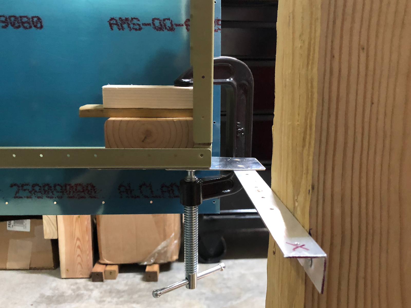
The tiedown bracket, which I had moved further down to keep there from being a gap between the bracket and the leading edge skin, was doing too good a job and was keeping the skin from lying flat against the spar.

My error was using a perfectly flat piece of aluminum against the spar flange to position the brackets when the leading edge skin actually curves inward here. If I'd had the foresight to do so then I would have test fitted the bracket with the curved skin before drilling.

No bueno.

Ah well, no big deal. A few minutes with the scotchbrite wheel to shape the bracket and now it fits.

Mucho mejor.

Now that things were fitting well I put in all of the skin the spar flange clecos to get the leading edge fully attached. Once all the clecos were in I grabbed the 12-inch #30 bit to back drill all of the ribs. The bit is sharp so it doesn't take very long, but getting the bit lined up perpendicular to the spar takes a bit of patience.


Moving on, the hole for the tiedown ring is too small and needs to be enlarged to accept the ring itself, so that became my next task. The plans state that this hole is supposed to be perfectly centered but my be a little off from project to project. I enlarged the hole just slightly so I could get a good look inside and was pleasantly surprised to find that the hole was indeed perfectly centered for me.

The verical line was an attempt to locate the center of the tiedown bracket before drilling. Good thing I didn't use it since it's completely wrong!

After using the unibit to enlarge the hole I went to test it with the stainless steel tiedown rings I bought from Cleaveland. I was having trouble getting the ring to thread into the bracket when I realized that the hole in the skin was actually too small for the ring. I'll need to enlarge the hole a bit more after the skin is removed from the skeleton since the tiedown bracket won't allow the hole to be made any bigger with it in place.


I moved on to the W-408 rib, which is the most inboard leading edge rib that I skipped earlier since it's blank. I deburred the edges and marked the centerline of the aft flange before slipping it into place in the side of the leading edge skin. The rib is horribly warped from the forming process, so I used a sharpie to mark where each hole will line up so I could flute the rib in between the holes.


With the rib fluted I had a much better time getting it in its proper place. I carefully lined up the line I had marked earlier with the holes in the web of the spar, then I used the 12-inch #30 bit to match drill the holes in the aft flange of the rib. The results were acceptable.

...and by acceptable, I mean near-perfect. Carefulness pays off!

Before I could match drill the holes into the rest of the rib flange, I needed to fabricate the joint plate that will allow the fuel tank to attach to the leading edge. Van's includes a couple of aluminum strips that are already cut to size, so all I had to do was bend one in the shape of the rib so it could be slid into place.


Bending the strip was easy. Getting it into place was not.

It took nearly 30 minutes of trial and error to get the strip wedged in place between the skin and the rib. The strip isn't perfectly shaped to the curve of the rib and the skin so there's interference near the front of the leading edge that required a good amount of coaxing and force to overcome.

This is exactly what I was after: 11/16" of the joint plate exposed on both the top and the bottom. It took a while to get to this point...

Moving the tightly-wedged strip tends to also move the rib, meaning it was difficult getting the strip to match the dimensions called out in the plans while also making sure the rib didn't move out of its proper place. The last thing I want is for the rib to end up with holes that don't have minimum edge distance, so I agonized over getting everything as close to perfect as I could.


Eventually though, everything was in place. I could finally take a step back and start getting an idea of the scale of the finished wing.

February 23, 2020

Match drilling wing skins

Now for the fun part - match drilling the hundreds of holes in the wing skins! Let's table the fact that I'll have to deburr every one of these later and just enjoy accomplishing something for now.

Since all of the holes are prepunched there aren't actually any holes to drill, or are there? Turns out there's a hole missing in my right wing spar! A quick change from the #40 reamer to a #40 bit quickly took care of that.

Guess that computer-aided manufacturing isn't always perfect. Not a big deal, fortunately.


As I finished the top skins and went to attach the bottom skins, I realized that my original design for the outboard lower spar supports wasn't going to work for the same reason the upper support angles wouldn't work. Reluctantly, I clamped the skeleton to the upright 4x4s and carefully removed the supports to modify them to allow the lower skins to go on without interference. With the top skins held in place with a couple hundred clecos, the skeletons stayed perfectly still when I took off the clamps.


I borrowed the clamp orientation from some other builders' sites. It works well!

After modification, I put the supports back in place and clamped the skeletons back onto the supports. Getting the lower wing skins clecoed on and match drilled took the rest of my allotted time. Progress!

February 18, 2020

Fabricating lower spar supports and removing twist from the wing skeletons

The wing is pretty solid with just the angles and jacks supporting it but I still needed to make some supports for the rear spar for extra support and so the skeleton won't twist when being worked on.

My solution was very simple, just some 2x4 pieces with the cut up remains of the aluminum angle I used when I was sealing the trailing edge of my rudder. I decided to go a step further and rivet on some of the scrap aluminum skin to protect the rear spar, so I dimpled/machine countersunk the skins and angles as necessary.


With the additional supports in place I began the process of removing any possible twist in the wings. To start I loosed the lag screws on the main angle supports and did my best to level the spars before retightening the screws just so everything was starting off from a level state.

That should do. A digital level may have been better for this but this won't be how I make the final adjustments anyway.

With everything as level as I could make it I attached the requisite plumb bobs to the spars to check the distances between the strings and the rear spar. Making small adjustments and clamping as I went, I was eventually able to get each set of measurements for both wings within 1/64".


Sag and twist removed, clamped in place, and solid as heck, these skeletons are ready for their skins. I went to attach the inboard and outboard skins when I noticed that there was some interference with the outboard skin and the angle attaching the outboard rib to the wing stand.

Welp, looks like I forgot that there's a wingtip that's supposed to go here eventually and the skin extends a bit beyond the end of the spar to attach it. I'll need to cut down the attach angle to allow the skin to go on without interference.

Looks like I need to cut about 1 inch off each end so the angle fits inside the spar area.

I had just spent an hour getting these things set perfectly, and now I have to remove an angle? Ugh.

There was no way I was going to take the whole wing off of the stand at this point, so I needed to come up with a way to remove just the angle while keeping the rest of the wing in place. As a homebuilder, sometimes you need to get creative to solve problems.

It looks janky as heck but this contraption keep things secure.

One removed angle...

...and cut to size. Much more better.

The removal and readdition of the angles unfortunately undid most of the work I had done earlier, so I spent another 30 minutes or so using plumb bobs to adjust and remove twist from the wings yet again. Better to worry about this now than later, after all.

With the skeletons and stands finally, 100% ready to accept the wing skins, I clecoed on the top inboard and outboard skins for both wings. Thanks again to my good buddy Chip at the airport who loaned me around 290 of his 3/32 clecos to supplement the 240ish I already have, allowing me to cleco all of the skins onto both wings at the same time. I went ahead and ordered an additional 100 from Cleaveland just to be safe.

These clecos saved the day. Thanks Chip!

One wing...

...two wings!

February 13, 2020

Riveting the left wing skeleton

Walking into the ship, I noticed that the hydraulic jack under the right wing had gone down a bit and allowed the assembly to sag. I'll eventually replace the jacks with some wood supports that won't compress over time, but the jacks will do for now as long as I keep an eye on them.

It's not much, but it's noticeably lower than before. Guess the seals in the hydraulic jacks aren't perfect.

In the meantime I worked on the left wing skeleton. Using the same method as for the right wing I riveted the ribs to the main and rear spars for the left wing and actually managed to do it in slightly less time. I did somehow manage to let the bucking bar get slightly angled on a couple rivets, causing some scratches on the spar. Those will need to be sanded out and primed, but they shouldn't cause any problems in the long run.

>:(

Same drill. I attached an angle to the outboard rib and once again got my dad's help to place the assembly on its stand.

Two wings!

With the jack in place and sag removed for now, I called it a night. I've made a lot of progress over the last few sessions and now I have a lot to show for it!

February 10, 2020

Mounting the right wing skeleton to the stand and removing sag

It's easy enough to set the inboard part of the main spars onto the angles on the wing stand but I can't really do that for the outboard end, which has the ribs flush against the outboard edge. To solve this problem, I cut some 1/8" aluminum angles to fit the width of the spar and drilled a couple extra holes in the outboard main ribs to attach the angles.


One wing skeleton, ready to go.

I cut some of the scrap aluminum sheet to protect the spar from getting scratched by the aluminum angle once it's mounted. With a little help, the spar was then mounted and clamped onto its stand.


I had picked up some hydraulic jacks from Harbor Freight (I couldn't find any screw jacks unfortunately) so I attached a 4x4 to one and used it to support the skeleton from under the center rib.

Saggy. Let's fix that, shall we?

To remove the sag I took some kite string (strong under load, thin, and easy to keep taut, so it worked just as well as fishing line would have) and ran it across the spar through the end holes with some clamps on each end to add weight and keep it taut.


From there it was a simple matter of raising the jack until the string lined up with all the holes.

Nope.

There we go.


With my workbenches cleared I went ahead and clecoed together the left wing. The shop looked rather inspiring at the end of the day.


February 9, 2020

FINAL final main spar nutplates, riveting the right wing skeleton

I had just clecoed all of the main ribs to the left wing when I noticed that there were three open holes in front of the wing walk area. As it turns out, these are the only three nutplates that will be used to bolt in the inboard fuel tank Z bracket to the web of the spar (the rest of the Z brackets use nuts rather than nutplates).


I vaguely remember debating whether I needed to install these back when I was installing the rest of the nutplates along the spar flanges, but I guess it slipped my mind. Reading ahead in the plans revealed that I don't actually need to worry about these until I'm working on the fuel tanks, but I decided to take everything apart and do them now. Space will be very limited in that area with the ribs installed so getting the job done now will give me way better access to everything.

I countersunk and primed the spar webs and used the backrivet set and plate to set rivets in each nutplate. Quick job done fast.

You may notice the larger AD4 rivet on the left spar. I forgot to reset the countersink cage and cut the spar way too deep for an AD3 rivet, so I went up a size. The AD4 rivet works just fine here.


Onto the main event - riveting the main ribs!

As I clecoed the main ribs on again I noticed that there were gaps between the rib and spar flanges, probably because the flange tool I made overbent the flanges. A quick rebending with the hand seamer and everything was flush again.


No good, but at least it's an easy fix.

Once the main ribs were all attached I had to come up with a game plan for getting this thing fastened together. It's suggested to use an offset rivet set for the ribs, but past experience has taught me that I HATE using the offset rivet set and that I wanted to use the straight AN470 set as much as humanly possible.

To facilitate this I decided to slightly flex each rib enough to fit the rivet gun and shoot the middle three rivets with the straight set. This way, I only have to use the offset one for the top and bottom two rivets, hopefully avoiding a substantial amount of pain and suffering. I left the rear spar off to allow the ribs to flex out of the way since they wouldn't have been able to otherwise.

I'm happy to say that my plan worked as intended and resulted in only a couple of squashed factory heads accompanied by fervent cursing as I drilled them out and replaced them. I still hate using the offset rivet set but at least the job is done.


The ribs for the wing walk area are too close together to comfortably fit the rivet gun. Thankfully the three inboard ribs all face the same way so it was easy to only attach and rivet one rib at a time, giving me plenty of room to work.


Lots of tape to protect the spar.

The plans specifically state to put the factory head on the rib flange to avoid distorting the parts, but I still ended up with a little deformation here and there. 

With the main ribs all riveted to the main spar, I attached the rear spar and was getting ready to start riveting when I noticed that I hadn't dimpled the small one-hole rib flanges that fit onto the bottom flange of the rear spar. It would be difficult to dimple two relatively thick layers of aluminum at once, so I took the whole thing off and dimpled the corresponding holes before reattaching the rear spar.

It was then that I took another look at the plans and noticed that the rivets for the outboard rib would need to be flush. Only one problem with that - I never dimpled those holes and that would be THREE layers of aluminum to dimple at once. Oooooookay, machine countersinking it is.

Countersinking for the flush rivets went smoothly, except the cage was too big to let the bit reach to top hole. Thinking quickly, I grabbed my electric screwdriver and improvised.


Thankfully all of the rivets on the rear spar can be set with the rivet squeezer, which made it a downright delightful experience compared to the main spar.

While taking a break from squeezing rivets I got curious and laid a wing walk doubler on the ribs just to see what it would look like.

Exciting!

Finishing up the rear spar, my right wing skeleton was done! Now, to get this thing onto the stand...