The angles have two distinct shapes that the builder must make: one side of the angle fits into the leading edge of the inboard fuel tank rib while the other is a simple rounded shape that will bolt to another angle coming off the fuselage.


For the other side I did my best to match the shape and dimensions in the diagrams.

I happened to have a compass in my tool chest that made it easy to etch a nice 1-inch radius per the plans.


To start, I cut the single angle into the two angles I'll need. The T-410 plates included in the kit are already shaped and fit nicely into the leading edge, so I traced their shape onto each piece.

For the other side I did my best to match the shape and dimensions in the diagrams.

I happened to have a compass in my tool chest that made it easy to etch a nice 1-inch radius per the plans.

 |
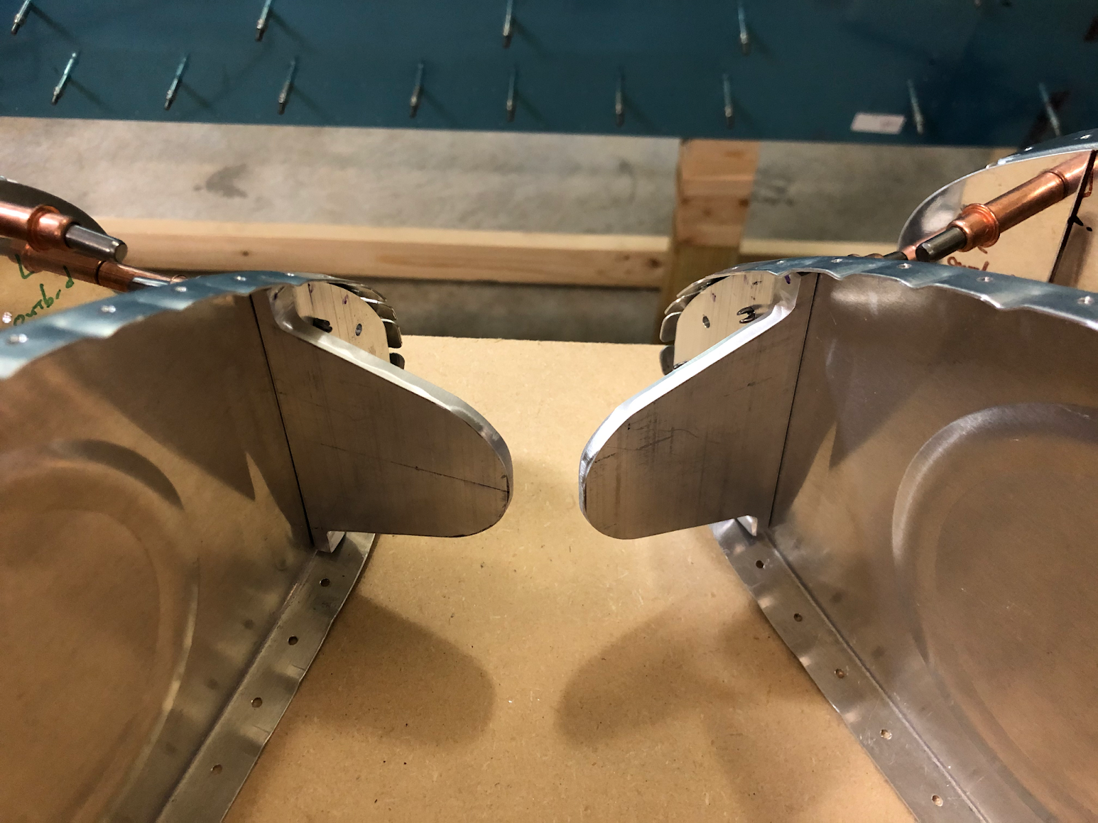
| Ready to cut. |
I used the bandsaw to start, cutting around the marked lines to get the angles to their rough shapes.

From there I used a combination of the vixen file for removing the most material and the scotchbrite wheel for final shaping and polishing.

Once I was happy with each shape, I test fitted them into the inboard ribs. The fit doesn't have to be perfect since the positions of the angles that attach to the fuselage will be determined by these angles.

Moving on, I started work on the T-410 plates. These are the plates that will seal and reinforce the inboard and outboard tank ribs at the leading edge, so they're shaped to fit the skin. They come attached to the inside of the T-407 rings that will reinforce the large cutout I'll soon be making in the inboard ribs. Apparently builders used to have to fabricate the plates themselves, but Van's realized they had enough room to just cut them from the same piece as the ring. Whether or not that's true, it still means more efficient manufacturing, less wasted aluminum, and less fabrication for the builder - a win all around!

Once separated and deburred, I removed the vinyl from each then reassembled each fuel tank so I could check the fit for each plate.
 |
| Without the plates, you can easily see how many open spaces there are here. |
 |
| With the plate in place inboard the rib, most of that space is filled and the remainder will be closed and sealed when the tank sealant is applied during final assembly. |
I can't really clamp the plates in place with the skins in the way, so I marked the location of each plate with sharpie so they would be in the right position when match drilling them to the ribs.

For drilling the plates, the plans don't really give a hole pattern. I decided to go with something similar to the pattern that the plans suggest for the T-405 angles. This pattern as is works for the angles, but it accommodates the angle portion and thus doesn't completely cover the area of the T-410 plates. The inboard T-410 plates have to use the same pattern since they'll be attached using the same rivets as the T-405 angles, but I decided to modify the pattern a bit to cover the whole area of the outboard plates.

These plates are technically meant to be installed after the inboard and outboard ribs have been riveted into the skins, so when making the modified pattern I wanted to ensure that any dimples and rivet heads coming inward from the skin wouldn't interfere with the rivets for the plates. To do this, I made sure that the holes I drilled would allow the straight rivet set to clear 1/8" from the edge of each plate. Each skin-to-rib dimple+rivet shouldn't encroach more than 3/32" inward from the inside face of the rib flange, so 1/8" gives ample clearance for the set when the plates are being riveted.

After punching and drilling one plate I clamped the other one to it and match drilled for a perfect match. The final pattern for the outboard plates looked something like this.

I positioned the plates on their ribs and match drilled the pattern.


The process is much the same for the angles. While test fitting the angles to the ribs I marked where the rivets would interfere with the angles and made sure to keep the rivet pattern away from these areas. The aftmost row of rivets had to be moved up a bit to ensure that the flat underside of the rivet heads wouldn't interfere with the curved transition to the flange of the angle.

Again I drilled one angle then clamped on the other one for match drilling.


I then clamped each angle to its rib and match drilled.

To finish the job, I removed the angles and clamped on the reinforcement plates so I could match drill using the holes I had just put into the ribs.